Fanuc 6064 Drive: Correcting Alarm 33
Step 1
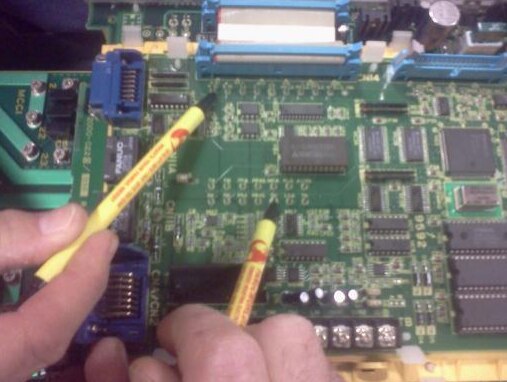
First, check all the jumpers, especially the S5 jumper.
Step 2
Apply three-phase power to the drive and turn on the control.
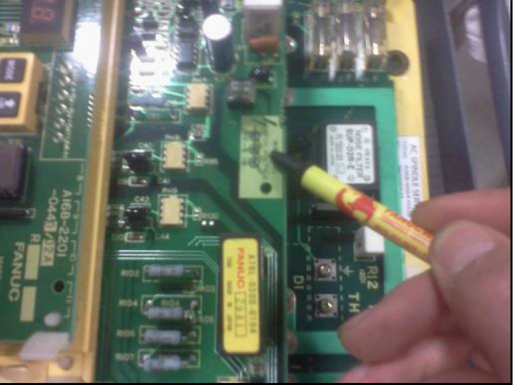
If the drive comes up with a display, then check test pins VDC and SDC to the ZERO volt test pin. All three pins are located on the A16B-2201-0440 PCB, which is the one with the LED display. The VDC to ZERO volt test pin reading and the SDC to ZERO volt test pin reading should both measure close to 3 volts DC.
If the above readings are not correct, then measure the DC voltage between the B+ and B- test pins. The B+ and B- test pins are located on the A20B-2000-0220 PCB. There should be 300 volts DC across those pins. If there is not 300 volts DC, then the top board is not getting the proper voltage it needs to work. If there is 300 volts DC, then there is probably a problem with the alarm circuitry on the drive. If the 300 volt DC is not correct, please verify that the LEG-TO- LEG and LEG-TO-GROUND AC voltage into the drive is correct.
Make sure that you can hear the contactor in the drive engage.
Was this helpful?
1 / 0