A single misconfigured parameter can sideline a CNC machine for hours. A corrupted NVRAM chip can turn a routine power cycle into a full day of troubleshooting. And a dead encoder battery, left unchecked for too long, can erase every stored reference position on the machine. These are the kinds of failures that Fanuc drive initialization is designed to prevent.
If you work with CNC equipment powered by Fanuc controls, understanding how to initialize a Fanuc drive correctly is one of the most important skills you can develop. This guide breaks down the full initialization process, explains the difference between servo and spindle startup procedures, and walks through the most common Fanuc drive issues technicians encounter on the shop floor.
In This Article
- What Is Fanuc Drive Initialization?
- Why Proper Initialization Is Critical
- The Fanuc Drive Initialization Process: Step by Step
- Common Fanuc Drive Issues and How To Solve Them
- The Fanuc Mastering Procedure: When and Why It Applies
- Preventive Steps To Avoid Initialization Problems
- Keep Your CNC Machines Running With the Right Fanuc Drive Partner
- Find the Fanuc Drives You Need With T.I.E. Industrial
- Frequently Asked Questions
What Is Fanuc Drive Initialization?
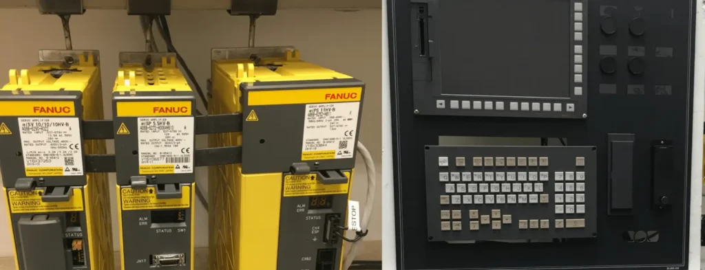
Fanuc drive initialization is the process of setting up and configuring the Fanuc drive system within a CNC machine. The Fanuc drive system controls the movement and positioning of the machine’s servo motors and spindle motors. When you power up a CNC machine for the first time, swap out a drive component, or restore parameters after a failure, you need to go through initialization to bring the system online.
During this process, you configure the CNC control to communicate properly with each amplifier module. You assign motor types, set speed limits, define acceleration rates, and calibrate feedback devices. Without a correct Fanuc drive initialization, the control has no reliable way to command motor movement or verify position accuracy.
Why Proper Initialization Is Critical
An improperly initialized Fanuc drive system can produce symptoms that range from subtle to catastrophic. Axis drift, positioning errors, spindle speed irregularities, and unexpected servo alarms can all trace back to initialization problems. In some cases, a misconfigured drive will cause the motor to behave unpredictably or produce excessive torque, which can damage the motor and the machine.
Initializing Fanuc drive system parameters correctly protects your equipment, your operators, and your part quality. It also saves time. Technicians who understand the full initialization sequence spend far less time chasing intermittent alarms and phantom errors down the road.
The Fanuc Drive Initialization Process: Step by Step
The steps below outline the general approach to initializing a Fanuc drive system. Keep in mind that specific parameter numbers and procedures vary by control series (0i-F, 30i, 31i, etc.) and by amplifier type (Alpha i, Alpha iS, Beta i). Always consult the Fanuc Startup Manual and Parameter Manual for your specific configuration.
1. Power-On Sequence
Fanuc drive initialization begins with a controlled startup. Turn on the main power to the cabinet first, then press the ON button on the CNC control panel. Wait for the initial display screen to load completely. The indicator light on the power supply module should activate, and the cooling fan should begin spinning. If the system enters an emergency stop state on power-up, verify that all E-stop buttons and safety interlocks are released before continuing.
2. Servo Parameter Initialization
Servo initialization tells the CNC control what type of servo motors and amplifiers are connected to each axis. On Fanuc systems, this typically involves the servo setting screen, where you specify the motor model, amplifier type, and axis assignment for each drive.
For Fanuc αi series servo amplifiers, the system uses Motor ID numbers stored in the servo parameter manual (B-65270EN). You enter the correct Motor ID, and the control loads the appropriate gain settings, current limits, and velocity parameters for that motor. If the Motor ID does not match the physical motor installed, the drive may trigger an invalid servo parameter alarm or produce unstable motion.
After entering the Motor ID, cycle the CNC power off and back on. The control will write the initialized parameters to memory. You can verify successful initialization by checking the servo diagnostic screen, where each axis should show stable position feedback with error values settling to ±1 pulse within roughly one second
3. Spindle Parameter Initialization
Spindle initialization follows a separate procedure from servo initialization. If you use a Fanuc spindle motor, start by entering the correct motor model code into parameter No. 4133. Then set parameter No. 4019, bit 7 to 1 to trigger automatic spindle parameter initialization. After making these changes, power off the CNC and the amplifier, then power them back on.
The automatic initialization function loads speed command parameters, detector settings, and operational mode parameters specific to the installed spindle motor. If there is a gear reduction ratio between the spindle motor and the spindle shaft, you will need to manually adjust parameters No. 4056 through 4059 (and No. 4171 through 4174 for noninteger ratios) to reflect the actual mechanical configuration. The standard parameter file assumes a 1:1 direct connection.
4. Feedback System Calibration
Every Fanuc drive system relies on feedback from encoders (pulse coders) or external scales to verify motor position. During initialization, you must confirm that the control recognizes the correct feedback device for each axis.
For machines using absolute pulse coders, verify that the APC (Absolute Pulse Coder) parameter is set correctly (parameter No. 1815 on many control series). Make sure the encoder battery is connected and holding voltage before cycling power, because if the battery is dead or disconnected during a power-off state, the system will lose all stored position data and require a full reference return.
For machines with dual feedback (motor encoder plus external linear scale), confirm the separate detector parameters and the weighting the control gives to each feedback source. Dirty or damaged scales are a frequent cause of servo oscillation that technicians sometimes mistake for a tuning problem.
5. Drive System Synchronization and Reference Return
Once you have completed servo and spindle parameter initialization, the next step in initializing Fanuc drive system components is to establish the machine’s reference position. This process, called reference return or zero return, tells the control where each axis sits in relation to the machine coordinate system.
Drive system synchronization depends on accurate reference positions. Without completing this step, the CNC cannot coordinate multi-axis movements, apply stored work offsets, or execute tool changes reliably. On machines with absolute encoders, the reference position is stored in battery-backed memory and persists across power cycles, as long as the encoder battery remains healthy. On machines using incremental encoders, you must perform a manual reference return after every power cycle.
6. Safety Verification
Before releasing the machine for production, verify all safety functions. Test the emergency stop circuit by pressing each E-stop button and confirming that the drives de-energize. Check that software-defined stroke limits are active and correctly set. If your machine uses a Programmable Machine Controller (PMC) for safety logic, confirm that the PMC ladder is running and that all safety I/O signals are reading correctly.
Common Fanuc Drive Issues and How To Solve Them
Even with a careful initialization, Fanuc drive issues can surface during startup or in the weeks following a drive replacement. Below are the problems our technicians encounter most frequently, along with practical solutions.
NVRAM Corruption on Spindle Drives (Alarm 17)
One of the most common Fanuc drive issues on older digital spindle amplifiers (A06B-6055, A06B-6059 series) is NVRAM corruption, which produces an AL-17 alarm on the 7-segment display. This typically happens after an incomplete or unstable power-down that allows the CPU to write bad data to the NVRAM chip.
To resolve this, you need to initialize the NVRAM using the adapter PCB (A20B-9001-0030). The procedure involves removing the NVRAM chip, installing the adapter, setting the jumper to the SET position, and following a specific button sequence on the keypad to restore factory defaults. After initialization, you must re-enter all machine tool builder (MTB) spindle parameters (F-00 through F-40). Parameters F-41 through F-53 must stay at their default values.
Pro tip: Record your MTB spindle parameter settings before you have a problem. Having those values on hand turns an NVRAM initialization from a multi-hour ordeal into a 30-minute procedure.
Absolute Position Data Loss After Battery Failure
Fanuc servo amplifiers use lithium batteries (typically the Panasonic BR-2/3AGCT4A, Fanuc part A98L-0031-0025) to maintain absolute encoder position data when the machine is powered off. When these batteries die, the control triggers an APC alarm (300-series alarms such as 307 or 308) for greater precision on the next power-up, and all stored reference positions are gone.
The fix requires replacing the battery and then performing a full reference return (home position reset) for every axis. Always replace encoder batteries with the machine powered on and in the emergency stop state. If you replace them with the power off, you will lose the position data you are trying to preserve.
We recommend replacing all servo amplifier and CNC control batteries annually as part of your preventive maintenance program. The cost of a battery is negligible compared to the downtime required for a full re-homing procedure.
Inconsistent Power Supply
Voltage fluctuations and unstable incoming power cause erratic behavior during Fanuc drive initialization. Symptoms include random servo alarms on power-up, failed initialization sequences, and intermittent drive faults that clear after cycling power.
Install a voltage regulation device or line conditioner upstream of the CNC machine to stabilize incoming power. Verify that the facility’s electrical infrastructure meets the voltage and grounding specifications in the Fanuc connection manual (B-64302EN) for your control series.
Faulty or Degraded Feedback Cables
Damaged motor feedback cables produce symptoms that mimic drive failures. You might see servo alarms, position drift, or oscillation that appears random. Because the cable carries the encoder signal between the motor and the amplifier, any intermittent break or short can make the drive behave unpredictably.
Inspect all feedback cables for physical damage, particularly at connector pins and where cables pass through cable carriers or tight bends. If you suspect a cable fault, swap it with a known good cable before condemning the drive or motor. Fanuc motor feedback cables degrade over time due to flexing and environmental exposure, so include them in your periodic inspection routine.
Software Compatibility After Control Upgrades
When you upgrade a Fanuc CNC control or replace a main CPU board, the control software version may not match the installed Fanuc drive system. This can prevent initialization or produce communication errors between the CNC and the amplifier modules.
Before performing any control upgrade, confirm that the new software version is compatible with your existing servo and spindle amplifiers. Fanuc publishes compatibility tables in their maintenance manuals that cross-reference control series, software editions, and amplifier types. If you discover an incompatibility after the upgrade, you may need to update the amplifier’s firmware or replace it with a compatible model.
Servo Oscillation After Initialization
If an axis oscillates or hunts after you complete Fanuc drive initialization, the cause is often mechanical rather than electrical. Worn ballscrew couplings, insufficient guideway lubrication, dirty encoder scales, and excessive backlash all produce symptoms that look like a servo tuning problem.
Before adjusting any servo gain parameters, check the mechanical system first. Mount a dial indicator on the axis and jog it back and forth to detect play. Inspect couplings for fatigue cracks, especially on bellows-type designs. Clean the encoder scales and verify the readhead gap. Changing servo parameters to mask a mechanical issue will only make the problem harder to diagnose later.
Temperature and Environmental Factors
Fanuc specifies operating temperature ranges for both the CNC control and the drive amplifiers. Running outside those ranges, particularly in high-humidity or high-dust environments, can cause condensation on circuit boards, overheating of power modules, and premature failure of cooling fans.
If your shop has wide temperature swings or excessive airborne contamination, consider installing supplemental cooling, air filtration, or cabinet pressurization for the electrical enclosure. Check amplifier cooling fans regularly, because a fan failure alarm (often displayed after long shutdown periods) usually means the fan has seized or slowed below its minimum speed threshold.
The Fanuc Mastering Procedure: When and Why It Applies
The term “Fanuc mastering procedure” comes up frequently in conversations about Fanuc robots, where mastering refers to the process of calibrating joint positions so the controller knows the exact angular position of each axis. On CNC machines, the equivalent process is the reference return or home position procedure described above.
If you work with Fanuc robots on a CNC cell, the mastering procedure involves jogging each joint to its reference mark (typically the 0° position), recording the master counts, and running the calibration routine through the teach pendant. A quick mastering can recover calibration if the reference data was previously recorded, while a full mastering is required after motor replacement or encoder failure.
For CNC machines specifically, the concept applies when you lose absolute position data (from a dead battery or drive replacement) and need to re-establish the machine’s home position. The principles are the same: you need to tell the control where the axes are physically located so it can coordinate all future movements from that known reference point.
Preventive Steps To Avoid Initialization Problems
Consistent maintenance reduces the frequency of Fanuc drive issues and makes the initialization process smoother whenever it is required.
- Back up your parameters regularly: Use the CNC’s built-in data I/O function or a memory card to save a copy of all servo, spindle, and machine parameters. Store the backup off-machine in a secure location. If you ever need to reinitialize from scratch, having a clean parameter backup cuts recovery time dramatically.
- Replace batteries on a schedule: Do not wait for low-battery alarms. Replace the CNC control battery and all servo amplifier encoder batteries once per year. Mark the installation date on each battery so you can track replacement intervals.
- Document your configuration: Record the Motor IDs, spindle motor codes, gear ratios, and any custom parameter adjustments for every machine. When a technician needs to learn how to initialize a Fanuc drive on a specific machine, this documentation eliminates guesswork and prevents errors.
- Keep spare drives on hand: When a Fanuc drive fails unexpectedly, having a tested replacement ready to install minimizes downtime. The initialization process goes much faster when you can reference the settings from the failed unit.
Keep Your CNC Machines Running With the Right Fanuc Drive Partner
When a Fanuc drive fails, every minute of downtime costs you money. T.I.E. Industrial stocks over 100,000 CNC parts, including servo amplifiers, spindle amplifiers, and power supply modules, all backed by a one-year in-service warranty and same-day shipping. Review our Fanuc drive resources to learn more, or shop our collection today to get the right replacement part.
Find the Fanuc Drives You Need With T.I.E. Industrial
Frequently Asked Questions
How long does Fanuc drive initialization typically take?
On a straightforward drive replacement where you already have the correct parameters documented, initialization can take as little as 30 to 60 minutes. A full initialization from scratch on a new build or after a major control replacement can take several hours, depending on the number of axes and spindles that need configuration.
What happens if I skip the reference return after initializing a Fanuc drive?
The CNC will have no reliable knowledge of where the axes are positioned. This means work offsets, tool change positions, and software stroke limits will all reference incorrect coordinates. Running the machine in this state risks crashing the spindle into the workpiece, the table, or the fixture.
Can I copy parameters from one machine to another when initializing Fanuc drive system components?
Only if both machines use identical hardware configurations, including the same control series, the same amplifier types, the same motors, and the same mechanical layout. Even small differences in gear ratios, encoder types, or axis stroke lengths require parameter adjustments. Loading mismatched parameters into a Fanuc drive system can produce immediate alarms or, worse, subtle positioning errors that affect part quality.
Maintenance Tips for Prolonging the Life of Your Fanuc Amps
Extend the life of your Fanuc amps with these recommendations.
Troubleshooting Fanuc CNC FAQs about Common Issues and Solutions
Get quick answers to the most common questions about Fanuc systems.
Demystifying Fanuc Part Numbers: A Guide for Maintenance Managers Using Fanuc CNC Machines
Take a deep dive to get a better understanding of Fanuc CNC part numbers.
Was this helpful?
2 / 2